Voltage Controlled Oscillator Kit Instructions Circuit Diagram
BlogVoltage Controlled Oscillator Kit Instructions Circuit Diagram -Ring Oscillator -Crystal resonator •Design of oscillators -Frequency control, stability -Amplitude limits -Buffered output -isolation -Bias circuits -Voltage control -Phase noise. 2 Oscillator Requirements •Power source •Frequency-determining components •Active device to provide gain •Positive feedback The chip we will use is a 4046 chip. This is phase-locked loop IC. We will use the VCO portion of it to create our voltage-controlled oscillator circuit. The voltage-controlled oscillator, as its output, produces digital signals that can function as clock signals. In this circuit, we will connect the 555 timer to act as a voltage controlled oscillator. The connections are shown below. Voltage Controlled Oscillator (VCO) Using a 555 Timer. The voltage controlled oscillator (VCO) circuit that we will build using a 555 timer is shown below. The breadboard schematic of the above circuit is shown below.
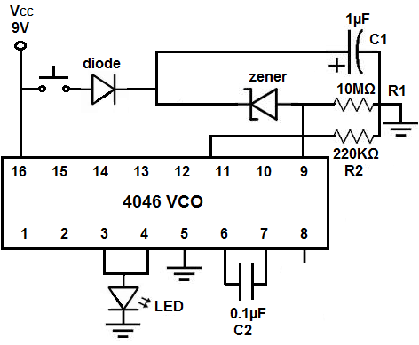
The circuit is constructed around a CD4046B phase-locked loop (PLL) integrated circuit with a built-in voltage-controlled oscillator (VCO). The voltage level at pin 9, value of capacitor C1 between pins 6 and 7, potentiometer R1 setting at pin 11, and potentiometer R2 at pin 12 control the frequency of the VCO. Theory: We are currently modulating voltage with a potentiometer. If the frequency is altered based on this change in DC voltage, a change in DC voltage from a different source should also modulate the frequency. Practice: You want the voltage from your sensing circuit to match the voltage range you identified by sweeping voltages above. If
How to Build a Voltage Controlled Oscillator (VCO) with a 555 Timer Chip Circuit Diagram
The value of output frequency is adjustable using the Control voltage (on pin 5) with a ratio of 10:1, which helps us in providing a wide range of control. Applications of Voltage Controlled Oscillators (VCO) Frequency Shift Keying; Frequency identifiers; Keypad Tone recognizers; Clock/Signal/Function Generators; Used to build Phase Locked Sensitivity to RF choke characteristics is common to all oscillator circuits that use chokes for shunt-feeding the DC operating voltage to the oscillator. References: 1. Alpha Industries - VCO Application notes. 2. Minicircuits - VCO Application notes. 3. Oscillator Basics and Low-Noise Techniques for Microwave Oscillators and VCOs - U.Rohde. 4. So this circuit is a common-base Colpitt's oscillator (the equivalence is illustrated in Figure \(\PageIndex{3}\)). Parasitic and design elements (especially \(L_{B}\) and compensating capacitors) in the active network may require that the resonant network present an inductance. As long as the Kurokawa condition is met oscillation will be stable.
