Three Phase Solid State Relay Circuit Diagram
BlogThree Phase Solid State Relay Circuit Diagram Learn how solid state relays (SSRs) use phototransistors and other semiconductor devices to switch AC and DC loads with optical isolation. Compare SSRs with electromechanical relays and understand their advantages and drawbacks.

Learn how solid state relays work, their advantages, and how to control them with DC or AC signals. See the circuit diagrams and examples of opto-isolators, SCRs, TRIACs, and transistors. There are two main types of relays: electromechanical relays and solid-state relays (SSR). Electromechanical relays are built with physical switches and electromagnets. While solid-state relays are built from solid state components, such as transistors, to perform the same function without any moving parts. Learn what a solid-state relay (SSR) is, how it works, and its features and types. Compare SSRs with mechanical relays and see examples of SSR circuits and applications.
Solid State Relay or Solid State Switch Circuit Diagram
Learn what a solid state relay (SSR) is, how it works, and how it differs from an electromechanical relay. Explore the various types of SSRs based on control signal, load type, switching characteristics, and output modulation.
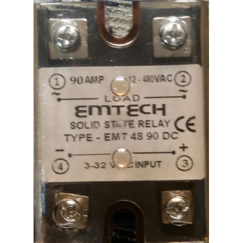
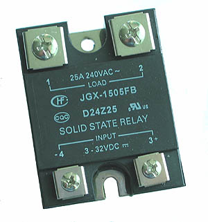
A solid state relay (SSR) is an electronic switching device that switches on or off when an external voltage (AC or DC) is applied across its control terminals. In AC circuits, SCR or triac relays inherently switch off at the points of AC zero cross when there is zero load current. What is a Solid State Relay? As the name implies, solid state relay (SSR) works on semiconductors. In contrast to an electromechanical relay which uses mechanical contacts to switch on or off a circuit, there are no mechanical contacts inside the solid state relay.. Switching is done swiftly through semiconductors like triac, transistor, diode, and thyristors. The solid state relay (SSR) is a safe, versatile, and industrial applications, there is an increasing need for low voltage or low current circuits to switch high voltage or high current circuits. While electromechanical relays (EMRs) have their place, solid state relays (SSRs) are often preferred due to their small size, lower cost, high

state relay Circuit Diagram
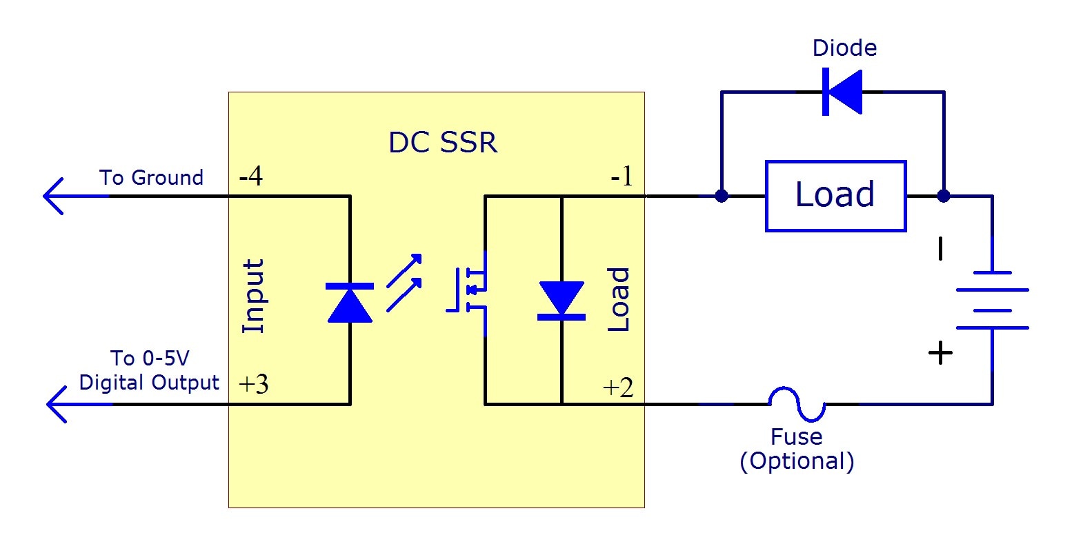
Learn about solid state relay (SSR), an electronic switching device that uses optocoupler to isolate the control circuit from the load circuit. Find out the different types of SSR relays based on input/output form, switching property and poles/throw form, and their advantages and disadvantages.