Temperature Based Fan Control Circuit Diagram
BlogTemperature Based Fan Control Circuit Diagram Then we will check if the temperature value is greater than 35 or not, if the temperature will be greater than 35, then the relay will be activated and the fan will start to rotate. Hardware Part First of all, make the connection of the LCD module with the Arduino as follows:
This instructable will take you through the steps necessary to create your own temperature controlled fan using an old computer fan. The materials that you will need are listed below. 1 x 12VDC computer Fan ($7.00 from Amazon) 1 x 120V / 12.6 V Transformer ($5.49 from radio shack) This paper presents the designs and the simulation of a DC fan control system based on room temperature using pulse width modulation technique, humidity and temperature sensor namely DHT11 with Arduino Uno Microcontroller. The fan will be used to reduce temperature of a room at certain level. To build the fan, we will use DTH11 Humidity Sensor. The user can monitor and control the system using a mobile or online application. The system is designed to be easy to use, low-cost, and energy-efficient. Similar systems have been the subject of numerous investigations in the past. For example, a proposed IoT temperature-based fan speed control and monitoring system using an

Based Temperature Monitoring and Automatic Fan Control Using ESP32 Circuit Diagram
The fan is based on Raspberry Pi 1 and 5V relay module. The system itself is broken down into 2 sub-circuits: 5V and 12V. He connects the 5V relay to Raspberry Pi 1 in order to control the higher voltage system that is connected to the fan itself. The temperature controlled feature lies in the combination of Raspberry Pi and the embedded
First Create a New Template. Assign the name, Hardware & Connection Type. From the Web Dashboard, Create 4 widgets Gauge, Label, LED & Slider. Testing: IoT Temperature Based Fan Speed Control System. After uploading the code, the ESP8266 will try connecting to the WiFi Network. After it gets connected to the WiFi Network, it connects to the Explanation: The NPN transistor acts as a switch, allowing the Arduino to control the fan. By adjusting the potentiometer, we set the threshold temperature at which the fan will turn on. Step 3: Connect the Potentiometer. Now, let's connect the potentiometer, which will allow us to set the threshold temperature for fan control.

Temperature Controlled Fan : 6 Steps Circuit Diagram
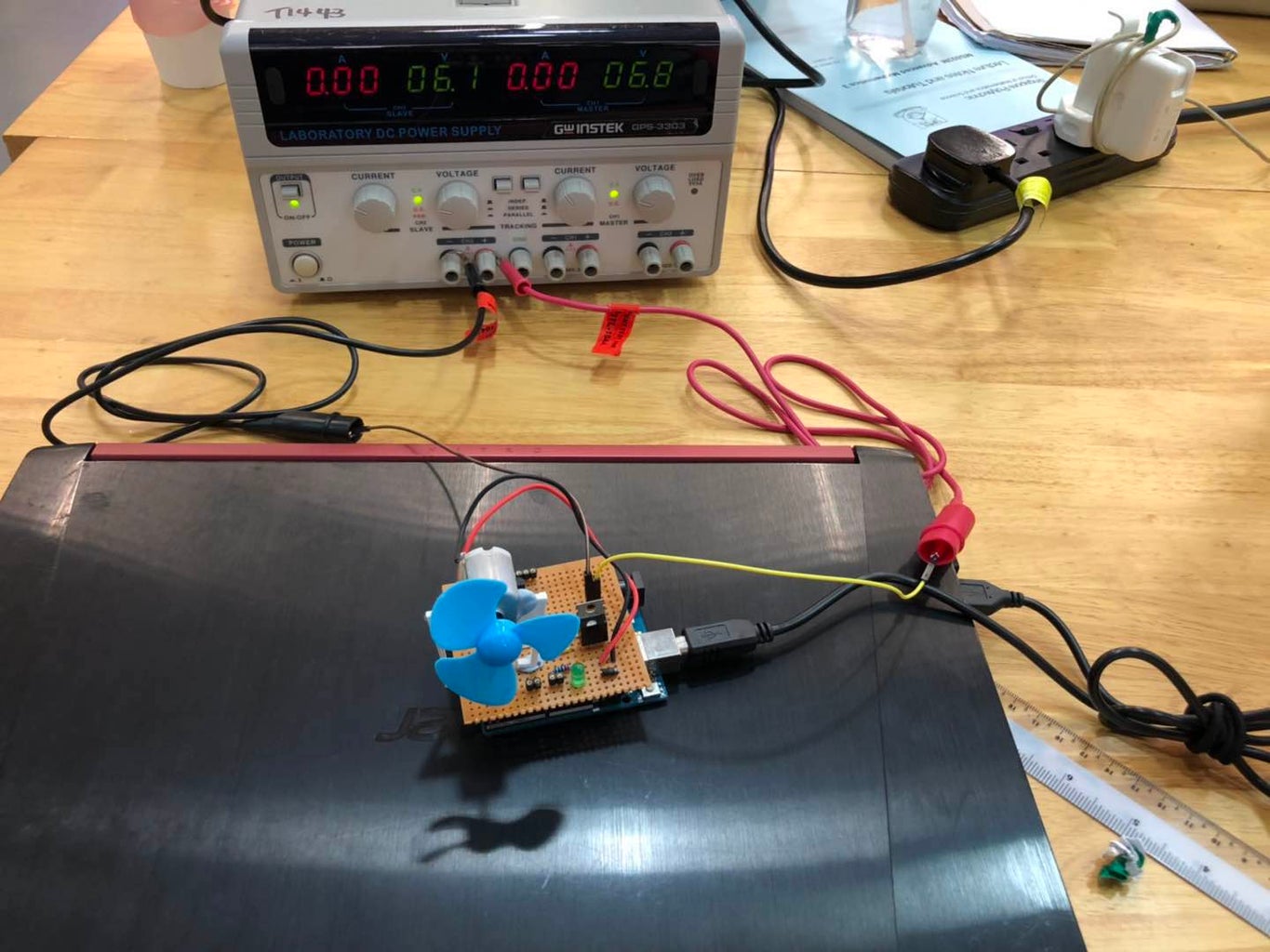
The fan speed is controlled by using PWM signals. And last part of the system shows humidity and temperature on LCD and Fan runs. Then we have programmed our Arduino according to the requirements. Working on this is very simple. We have generated PWM from Arduino and put it at the base terminal of the transistor.
