How to Make a Digital Voltmeter Ammeter Circuit Module Circuit Diagram
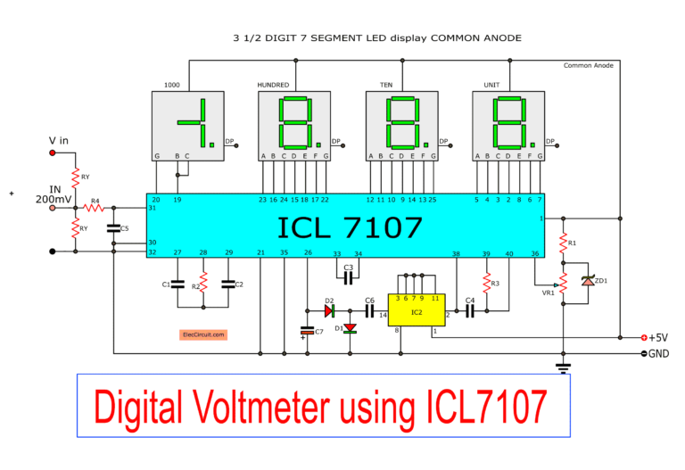
BlogHow to Make a Digital Voltmeter Ammeter Circuit Module Circuit Diagram Working of digital voltmeter circuit. Step 1: Transformer steps down the input AC voltage. Step 2: The voltage divider circuit ensures a voltage less than 5 v across the 4.7k resistor and hence maximum input a.c volts as already seen in the simulation must be 311 r.m.s volts. Needless to say, the IC L7107 can be also rigged into a simple yet accurate panel digital voltmeter circuit, which is what we are presently interested in. Circuit Operation. Referring to the circuit diagram below, the unit is a full fledged digital voltmeter circuit which can be used for measuring direct voltages right from zero to 199 volts. Section 1: Understanding the Basics of a Digital Voltmeter Circuit. A digital voltmeter circuit is an essential tool for measuring voltage in electronic circuits. This section will provide an overview of the basic components and principles involved in building a digital voltmeter circuit. 1. Analog-to-Digital Converter (ADC) The heart of a

Building digital voltmeter circuit Parts you will needs. IC1: ICL7017 IC2: CD4049, CMOS Hex Inverting Buffer/Converter D1, D2: 1N4148,75V 150mA Diodes ZD1: 2.4V 0.5W Zener diode 0.25W Resistors tolerance: 1% R1: 10K R2: 47K R3: 100K R4: 1M. VR1: 2K to 5K Trimmer Potentiometer. See modifying Digital 50V voltmeter. Capacitors Circuit Diagram and Working Explanation: Working of this Digital Voltmeter Circuit is very simple. ADC inside the IC is integrating converter or Dual type Analog to digital converter. Internal ADC of this IC reads the voltage that to be measured and compare it with an internal reference voltage and converts that into the digital equivalent.

How to Make a Simple Digital Voltmeter with an Arduino Circuit Diagram
Figure 1 - Arduino Digital Voltmeter Circuit Diagram Figure 2 - Arduino Digital Voltmeter Circuit Diagram Components. Arduino UNO 16 x 2 The components required and the construction of the project is very simple. The working of the project is explained here. In a digital voltmeter, the voltages to be measured, which are in analog form
After the end of this article, we will collectively build a digital voltmeter circuit that will ultimately make it cost-effective and precise. However, an ICL7107 is a 3.5 digit ADC converter analog to digital, which devours low power.
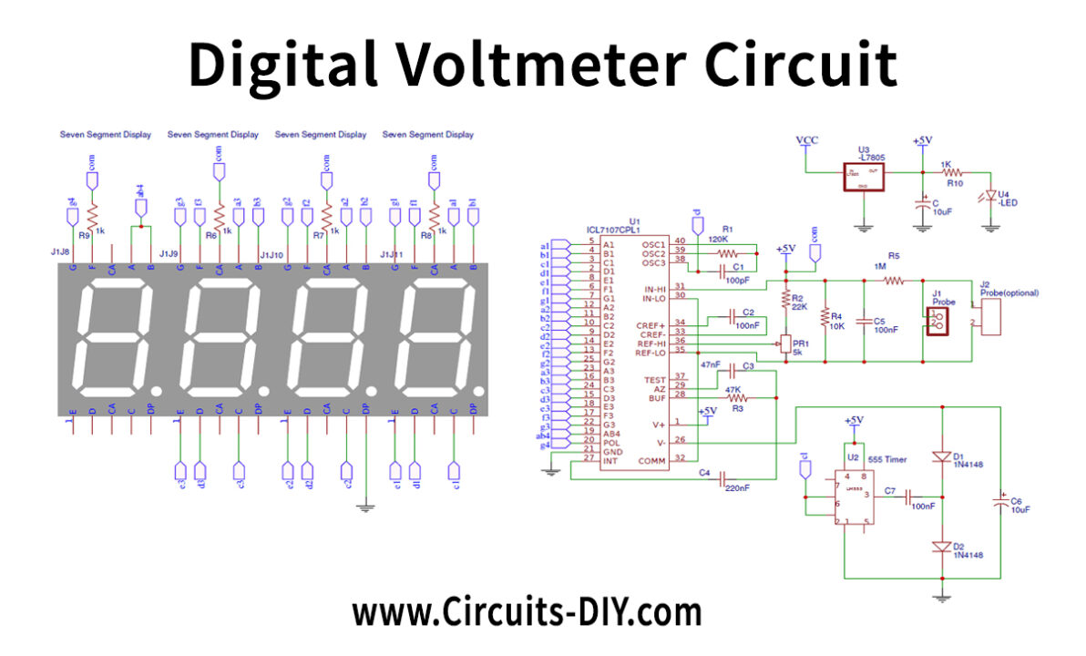
Digital Voltmeter Circuit Using IC L7107 Circuit Diagram
Courtesy of All About Circuits. It's easy to make a digital voltmeter. All that's needed is an Arduino and a 16x2 liquid crystal display (LCD). Using an Arduino to measure voltages is relatively simple. Inside the Arduino, there are multiple analog input pins connecting to an analog-to-digital converter (ADC).