How To Build A Simple Circuit At Home Step By Circuit Diagram
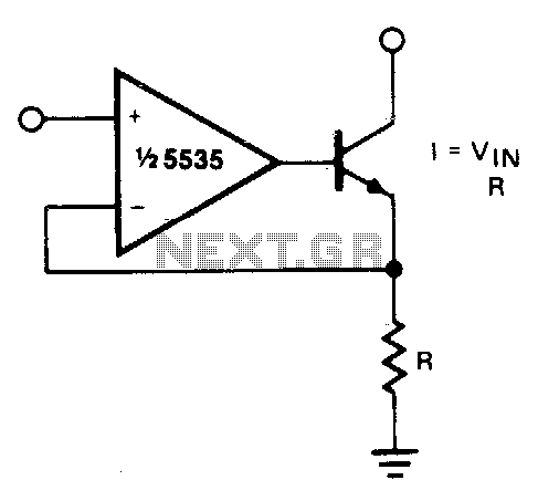
BlogHow To Build A Simple Circuit At Home Step By Circuit Diagram We can therefore construct a circuit that converts a voltage to a current. Looking at the datasheet for the LM324 we can see it's capable of driving 30mA and can therefore be used as the basis of our simple current source without an additional drive transistor. In addition to that we'd like a 0-10V or +/-10V output. Convert Current to Voltage. It is extremely simple to measure 0-20 mA signal with a device that will measure only Voltage inputs. If the Voltage input module available will accept a 0-10 Vdc signal, but may not accept a 0-20ma signal directly.

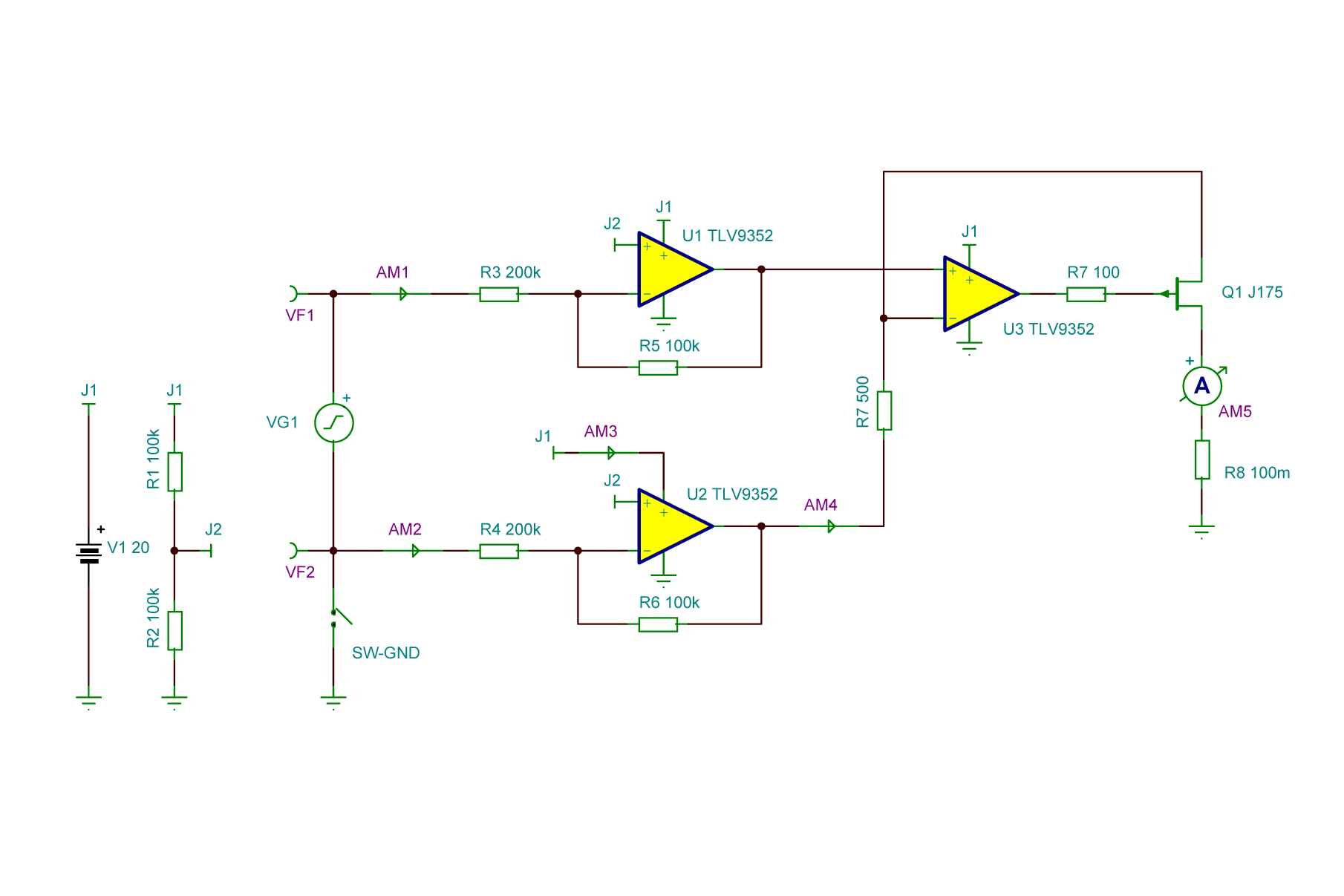
The output voltage from this circuit will range from 7.5V to 35V DC with 60mA Output Current. The AC-AC Converter is quite simple as in comparison to the DC-DC converter . This is because AC-AC Converter only implies a transformer that converts AC from one voltage level to another voltage level. There are many types of voltage-to-current and current-to-voltage converter circuits, and most of them use a combination of opamps and transistors to achieve a high level of accuracy. But when high accuracy isn't necessary, a simple converter of this type can be made using just one or two resistors.

Current and Current Circuit Diagram
How to Design a Simple Constant Current/Constant Voltage Buck Converter (1) Assuming a resistive load, Equation 2 governs the voltage at the output: (2) Equation 3 sets the voltage regulation level: (3) As seen in Figure 1, a Zener diode regulates the voltage in CV mode. Using a Zener as a voltage clamp
DC converters can also serve as switching mode regulators to convert a DC voltage, normally unregulated, to a regulated DC output voltage. Buy Now. This simple voltage booster circuit can boost the voltage of a 1.5V AA battery to 40V to 70V DC. The output current of the circuit is around 20mA. The circuit can work for any application

Current to Voltage Converter(I to V) Circuit Diagram
Circuit analysis of Current to voltage converter: The above circuit is a simple current to voltage converter, The non inverting terminal is grounded, and the inverting terminal is connected to a current source. current to voltage converter formula: now see the current flow in the circuit, analyzing the circuit using Kirchhoff's current law. Learn how to make simple boost converter circuits using transistors, and IC 555. These step up circuits will convert 1.5 V 3 V to 12 V, 24 V. You can use a 9V 5 amp transformer to build the voltage/current source for the LM317 circuit. You can try the following circuit for the mentioned purpose. Use only 2nos of 2N3055 in the circuit, that A boost converter (step-up converter) is a DC-to-DC power converter that steps up voltage (while stepping down current) from its input (supply) to its output (load). It is a class of switched-mode power supply (SMPS) containing at least two semiconductors (a diode and a transistor) and at least one energy storage element: a capacitor, inductor
In the test case 1, the input current across the op-amp is given as 1mA.As the input impedance of the op-amp is very high, the current start to flow through the feedback resistor and the output voltage is dependable on the feedback resistor value times the current is flowing, governed by the formula Vout = -Is x R1 as we discussed earlier.. In our circuit the value of Resistor R1 is 1k.