Electronics basics Diy electronics Electronic circuit Circuit Diagram
BlogElectronics basics Diy electronics Electronic circuit Circuit Diagram The digital potentiometer It will show how their functions, features, capabilities, and options can be used to simplify circuits, make circuits processor compatible, and reduce or even eliminate the need for bulky, less-reliable mechanical potentiometers. the digipot's internal topology consists of a simple serial string of resistors Potentiometer as a Rheostat. A potentiometer and a rheostat may seem similar but are not. Rheostat is one of the many applications of a potentiometer. Let's see what a rheostat is and how it differs from a potentiometer. What is a Rheostat? A device that is used to vary the resistance in a circuit is called a Rheostat. A potentiometer is a simple mechanical device that comes in many different forms. It provides a variable amount of resistance that changes as you manipulate it. The examples in this article uses a potentiometer with a twisting shaft, one of the more common versions of a potentiometer you will find.

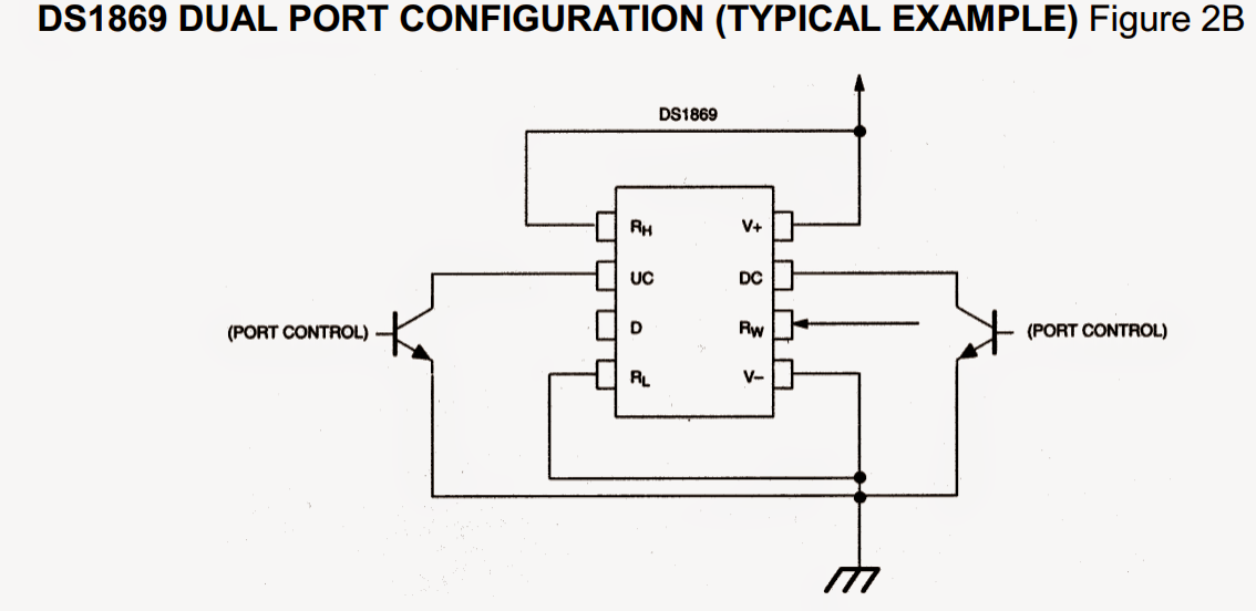
Digital potentiometers are just like any analog potentiometer with three terminals with only one difference. Whereas in analog one you have to manually change the wiper position, In case of digital potentiometer wiper position is set according to the signal given to potentiometer using any microcontroller or microprocessor.
4 Simple Circuits using Potentiometer Circuit Diagram
Hello, I'm looking for something like the Digital Potentiometer IC X9315 that a 3 wire hall effect sensor can be used as the input. 24v dc motor using china motor controller that has a 100k ohm pot for speed control. I want to replace the 100k pot with a digital pot that I can wire in the hall sensor as the speed controller. Thanks E That means they are difficult to use in place of a potentiometer which might be sitting anywhere in a circuit. If one end of the pot needs to be to ground and current only flows in one direction through the pot, then it will be a lot more straightforward. Way to make a simple digital Potentiometer Searching I found that there are digital Digital Potentiometer. A digital potentiometer is a chip where you can adjust the position of the wiper through digital signals, such as SPI or I2C. This can be very useful if you want to be able to change resistance on-the-fly from an Arduino or other microcontroller. For example to adjust LED brightness.

Look for a digital potentiometer with 1024 steps. Another solution is to use two potentiometers in series. For example, one pot could have a span of 100kΩ (course setting) while another pot could be 1kΩ (fine setting). You can also replace the course setting pot with high precision fixed resistors to span different test temperatures.
