Electronic control circuit temperature and relative humidity Circuit Diagram
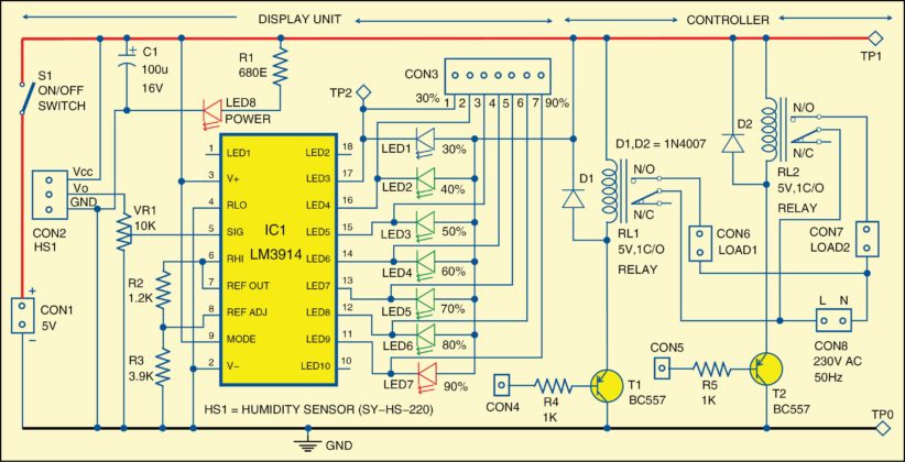
BlogElectronic control circuit temperature and relative humidity Circuit Diagram The 100p is "pulling against" a 4k7. A bad design. The operation of the circuit needs explanation. The first two transistors form a Schmitt Trigger. Diode D1 serves NO PURPOSE and can be removed. The designer of the circuit states that as the resistance between the two sensors decreases the circuit will latch the relay. This is NOT TRUE. Then it prints the humidity and temperature values to the serial monitor and waits for 2 seconds before doing the next reading. Applications. Relative humidity and temperature measurement devices ; Conclusion. We hope you have found this Interfacing DHT21 / AM2301 Temperature Humidity Sensor with Arduino Circuit very useful. Humidity sensor circuits may be part of a subsystem of a larger project or process. These sensor designs must provide accurate results with high resolution. Let's explore the basics of humidity sensors and their design. Humidity Sensors. Humidity sensors are employed for measuring the moisture or water content in an environment.

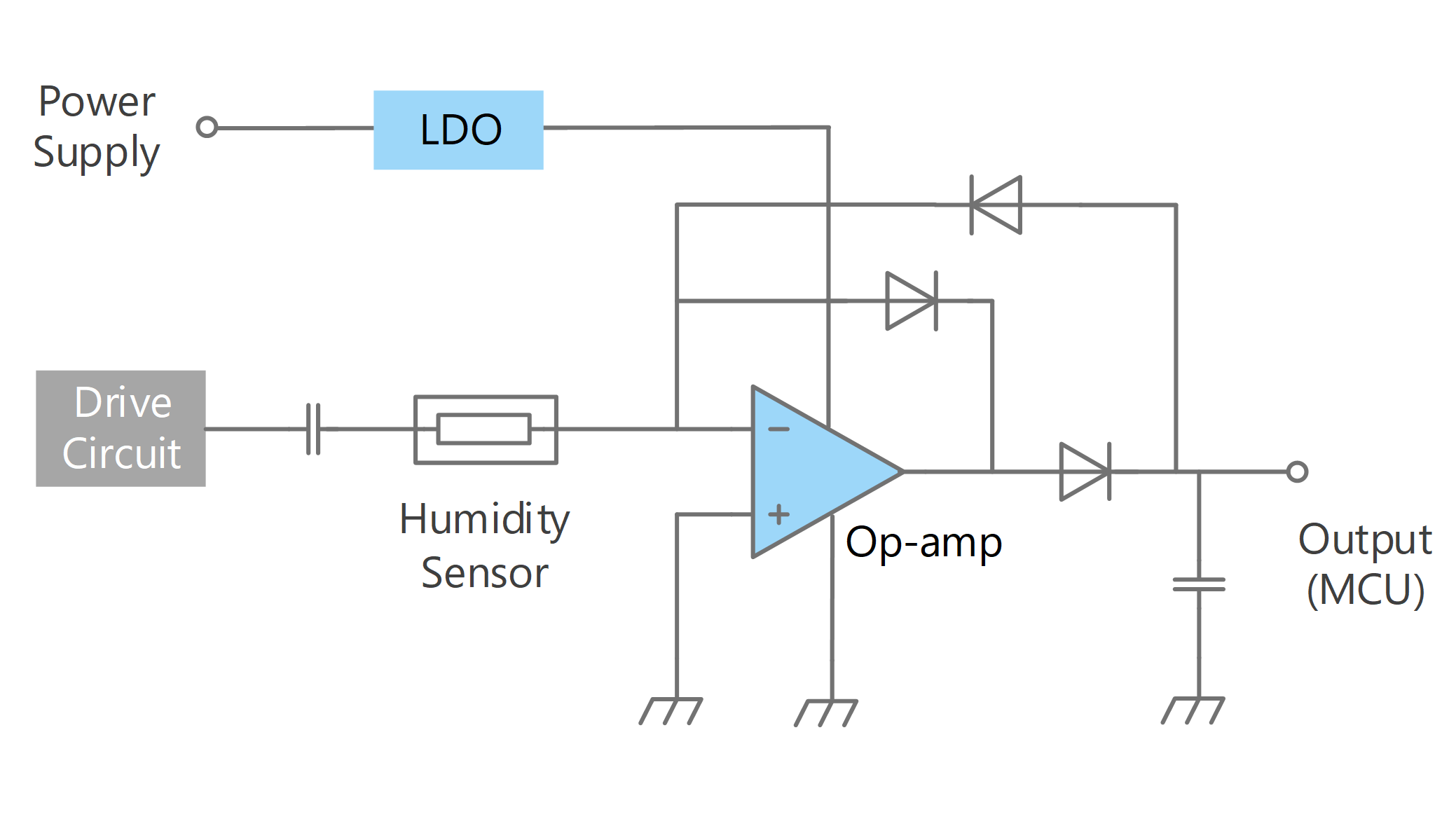
How to measure temperature and humidity with the DHT11 and an Arduino. Diagrams and code are provided to display readings on an LCD or the serial monitor. All I want is to design a circuit that could predict a rainfall or water and send a message to the user to his phone.Also keeping in mind about the humidity and temperature factors. the relative humidity measurement is dependent upon the particular humidity sensor selected; therefore, the data sheet must always be consulted to determine the correct formula. Capacitance-to-Digital Converter (CDC) The 24-bit . AD7745CDC measures capacitance by using a switched capacitor charge balancing circuit, as shown in Figure 2. The
PDF Relative Humidity Measurement System Circuit Diagram
To measure the surrounding air this sensor uses a thermostat and a capacitive humidity sensor. working of DHT11: DHT11 sensor consists of a capacitive humidity sensing element and a thermistor for sensing temperature. The humidity sensing capacitor has two electrodes with a moisture holding substrate as a dielectric between them.

The DHT11 sensor operates by utilizing a thermistor to measure temperature and a humidity-sensitive capacitor to gauge the relative humidity in the surrounding environment. When connected to an Arduino board, the sensor sends digital signals that can be interpreted to obtain accurate readings of both temperature and humidity levels. It uses humidity sensor DHT11 (that can also measure temperature) and Arduino UNO board. The desired humidity level can be set by potentiometer from 0 to 100%. The LCD displays set humidity level and actual humidity in the room in % of RH. Two LEDs are used to indicate humidity level is within set value or above-set value. CIRCUIT CONNECTIONS. 1. The DHT11 Humidity Sensor measures and outputs the relative humidity (RH%) of the surrounding environment. The formula (equation) of the relative humidity is as follows: Where RH is the relative humidity, ρ w is the density of water vapor at a certain temperature, and ρ s is the density of water vapor at saturation at that temperature.