Design of Sensor Data Processing Steps in an Circuit Diagram
BlogDesign of Sensor Data Processing Steps in an Circuit Diagram The necessity for real-time monitoring of Air Quality is very glaring. So in this project, we are going to build an ESP32 Air Quality Monitoring System using Nova PM SDS011 sensor, MQ-7 sensor, and DHT11 sensor. We will also be using an OLED Display module to display Air Quality Values. Testing and calibrating the sensor. The initial step involves calibrating the sensor. To achieve this, connect the sensor to the circuit and allow it to remain powered on for 24 hours to complete In this project we are going to make an IOT Based Air Pollution Monitoring System in which we will monitor the Air Quality over a webserver using internet and will trigger a alarm when the air quality goes down beyond a certain level Sensors and Transducers Semiconductors
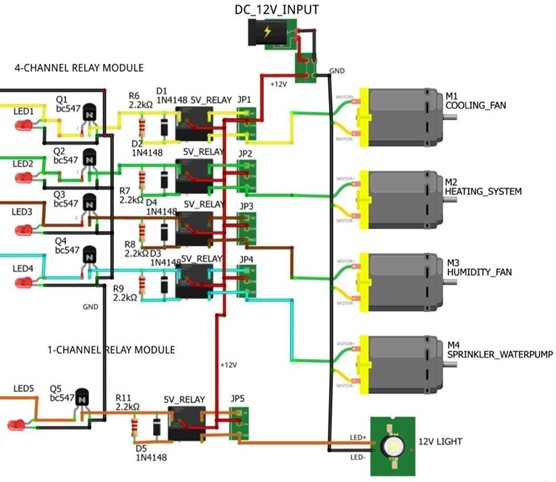
The complete air quality monitoring system project connection will be as follows with an OLED, DHT11 and MQ135 gas sensor connected to Arduino Uno on a breadboard. The arduino is connected to the OLED using I2C protocol with the help of the SDA and the SCL pins. here inside the mq9 sensor they are using the filament made by the co reactive element which reacts with the co. and in the presence of the co the conductivity will vary with thee carbon monoxide. that's why we are getting the different value in this air quality monitoring system project.. Gas Detection: The MQ-9 sensor is only designed for detecting carbon monoxide (CO) and some of the
Creating a Smart Air Quality Monitoring System with Java Circuit Diagram
In this tutorial, I will provide the essential details about the air quality index, the pinout of the MQ-135 sensor, and how to measure air pollution using the MQ-135 sensor. After this tutorial, you will be able to develop the air pollution monitoring and alert system using the Arduino Uno board with an MQ-135 sensor. DIY Arduino air quality monitor which can measure surrounding air quality also shows temperature and humidity in your room. Air Quality sensor (MQ135) Tools and machines. 1. 3D Printer (generic) 1. Soldering iron (generic) This is a 3D enclosure I design for the project. But you don't need a 3d printer for build one, you can make your Due to the high sensitivity and fast response time of it. But, in this design, we used the MQ2 sensor for the smoke situation. This sensor has four outputs, namely, Vcc, ground, D0, and A0. Architecture. Firstly, to make an IoT based Air Quality Monitoring system will be collecting the data from the mq2 senor and send to NodeMCU.

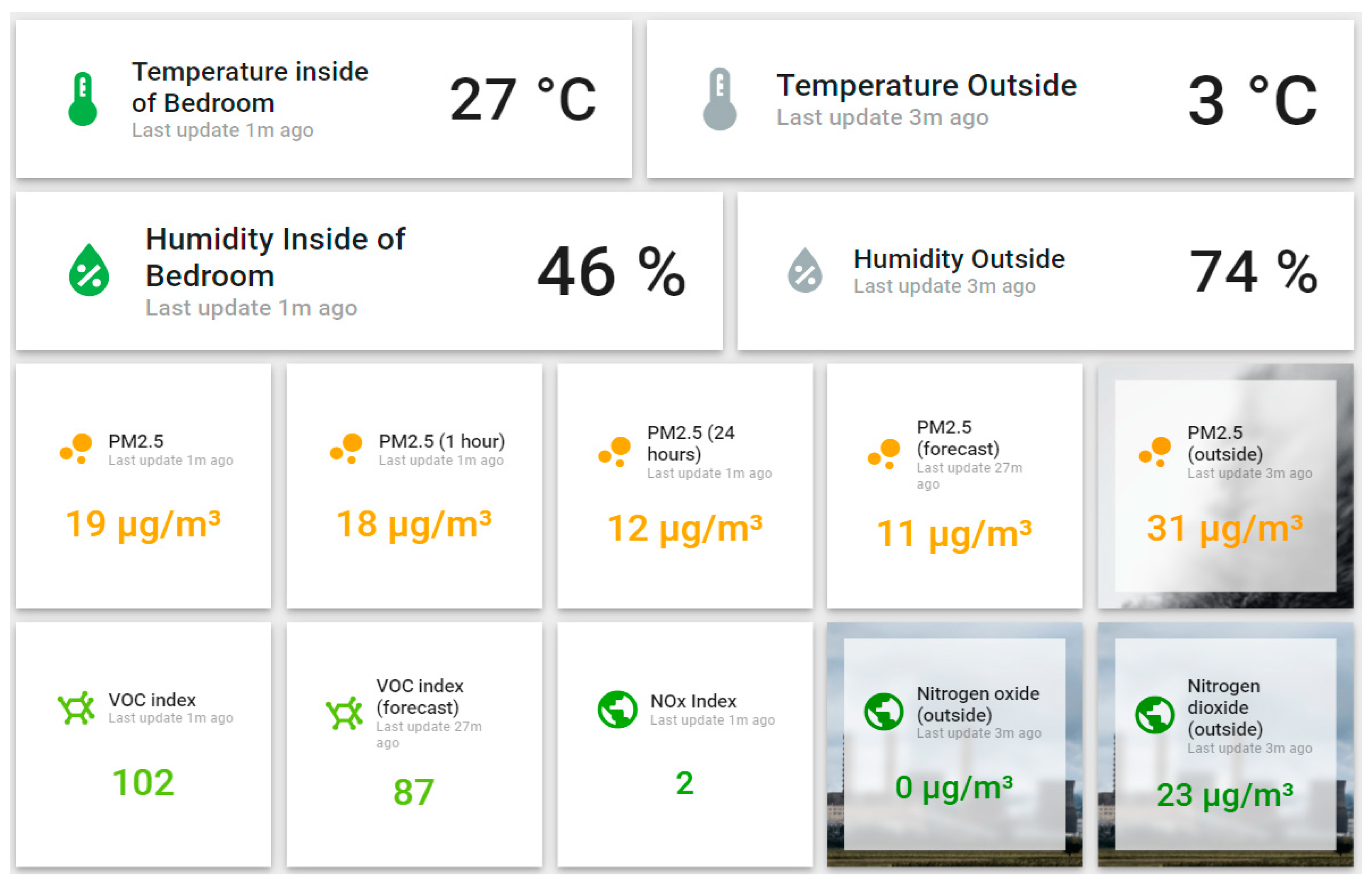
In this tutorial, you learned how to create a smart air quality monitoring system using Java and IoT components. You successfully connected a sensor and built an application to read and display air quality data in real-time. Next Steps. Explore additional sensors for humidity, temperature, and other pollutants.
Creating Your Own Air Quality Monitoring System with ESP8266 Circuit Diagram
In the Viam app, create a machine by typing in a name and clicking Add machine.; Click View setup instructions.; Install viam-server on the Raspberry Pi device that you want to use to communicate with and control your air sensor. Select the Linux / Aarch64 platform for the Raspberry Pi to control the air sensor, and leave your installation method as viam-agent.