Design A Long Range FM Transmitter Circuit Diagram
BlogDesign A Long Range FM Transmitter Circuit Diagram FM Adapter for your Car stereo:- A simple low power FM transmitter using transistor 2N222. This circuit application can come handy when you don't have an auxiliary input for your car stereo or car audio device. Versatile FM transmitter: This is a simple to make a circuit for an FM transmitter. This design doesn't include any coil. Test

How the FM Transmitter Works. The circuit is powered by a 9V power supply.Transistor Q1 is a high gain audio amplifier that amplifies the sound detected by the electret microphone.The output of Q1 is fed into the frequency modulating circuit created by transistor Q2, inductor L1, and variable capacitor C5.. This is a very high frequency (VHF) circuit, so you will want to use transistors with a
Easy FM Transmitter Circuit, 500m Simple And Best FM Transmitter Circuit Circuit Diagram
Description The circuit of the transmitter is shown in Figure 1, and as you can see it is quite simple. The first stage is the oscillator, and is tuned with the variable capacitor. Select an unused frequency, and carefully adjust C3 until the background noise stops (you have to disable the FM receiver's mute circuit to hear this). Circuit and Working. The simple FM transmitter is built around low-power audio amplifier using LM386 (IC1), transistor PN2222A (T1), 30MHz crystal (XTAL1), varactor diode 1SV149 (D1) and a few other components. Inductor L1 is a three-turn coil made with 20SWG wire that has 8mm diameter with half-turn taping. This simple and easy FM transmitter circuit can transmit the input signal gets from the microphone up to the 500-meter range area. Two NPN transistors and some discrete components are used in the circuit. You can use 3v to 12v DC power supply for this circuit. At low voltage, the range of this transmitter will be shorter.

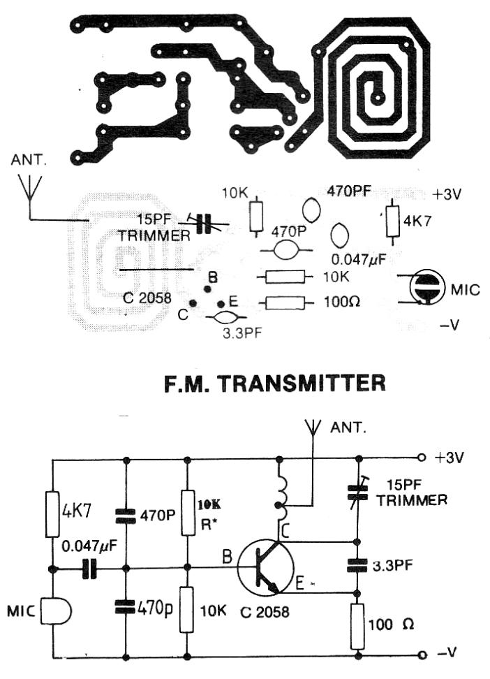
Building your own FM transmitter is a great way to experiment with electronics and learn more about how radio frequency works. This circuit is perfect for electronics hobbyists with some circuit experience from before. The Circuit. The circuit is based around a transistor with an LC tank circuit. Here's the schematic for the FM transmitter For the wireless spy transmitter circuit everything becomes pretty simple and you just have to hide the transmitter circuit in some suitable place, like under the table, couch, sofa etc. Parts List. R1 = 10K, R2 = 10k, R3, R4 = 27K, R5 = 1.5 M, C1 = 104, C2 = 220uF/25V, T1 = 188, T2 = 187, MIC = electret mic, IC1 = 741,Power = 9 volt battery FM transmitter is a low-power FM radio transmitter that communicates a signal from a sound gadget to a standard FM radio. Ordinarily, we need to make an FM transmitter that is easy to assemble and has a decent range. So here is a basic FM transmitter circuit that contains just a couple of parts and has a long range.
How to Build an FM Transmitter Circuit Diagram
Categories FM Transmitter Circuits, Simple Electronic Circuits Tags 2n3904, In this tutorial, we are going to design a Simple Doorbell circuit using a 555 Timer IC. It is a very common and useful device. FM transmitter is a low-power FM radio transmitter that communicates Read more Read more.
