Capacitor Filter Working Principle Circuit Diagram
BlogCapacitor Filter Working Principle Circuit Diagram The frequencies above the cut-off frequency of the circuit are bypassed to the ground by the capacitor C. This is a capacitive low pass filter which has a resistor connected in series and a capacitor in parallel with the output. The principle involved: the reactance of the capacitor is inversely proportional to the frequency applied, i.e., Xc For this circuit, with the values chosen, we build a bandpass filter that has a passband from 1KHz to 10KHz. If modifying these frequencies, then the values of the resistors and capacitors need to change. Passive Bandpass Filter Circuit. The passive bandpass filter circuit that we will build with resistors and capacitors is shown below.

This high pass filter circuit project filters a frequency spectrum or any mix of frequencies. The frequencies below the cut-off frequency of the filter are blocked effectively by the capacitor C. This circuit has a resistor connected in parallel and a capacitor in series with the output. The principle involved : the reactance of the capacitor is inversely proportional to the frequency applied
How to Build a Passive Bandpass Filter Circuit with Resistors and ... Circuit Diagram
This is due to the time taken to charge the plates of the capacitor as the input voltage changes, resulting in the output voltage (the voltage across the capacitor) "lagging" behind that of the input signal. The higher the input frequency applied to the filter the more the capacitor lags and the circuit becomes more and more "out of phase".

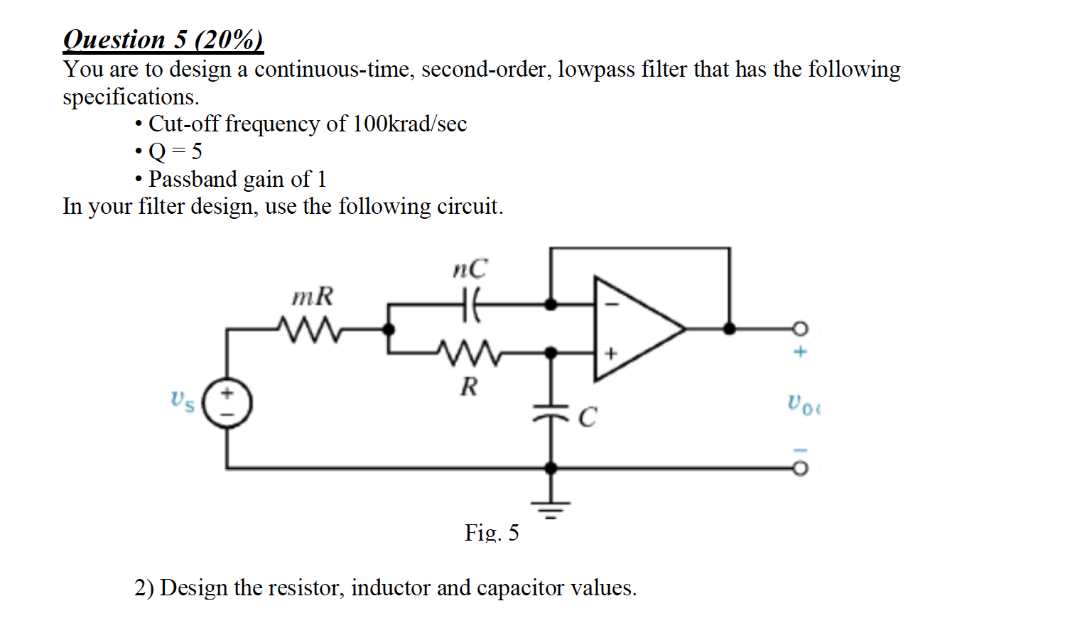
Filters are circuits whose response is dependent on the input voltage's frequency. Many crucial tasks in a system can be carried out by filter circuits. While resistors, capacitors, and inductors can also be used to create filters, op-amps, resistors, and capacitors are the main components of most filter circuits. filter is usually equal to the total number of capacitors and inductors in the circuit. (A capacitor built by combining two or more individual capacitors is still one capacitor.) Higher-order filters will obviously be more expensive to build, since they use more components, and they will also be more complicat-ed to design.
Why use a resistor in filter circuits Circuit Diagram
I explain how high-pass RC filters work using the falstad circuit simulator and a circuit which is similar to the one used with the low pass filters in a pre To create a low-pass filter using an R and L, we can start with an RC high-pass filter as shown in Figure 4 and swap the C for an L. We can also take the same type of approach to design a high-pass filter if we start with a RC low-pass filter as shown in Figure 2 and replace the C with an L. Both examples are illustrated in Figure 6. Figure 6.

Using capacitors and inductors can get you 2nd order filters. 2nd order filters have a more pronounced filtering characteristic. If you had a single resistor you cannot call it an attenuator - two resistors are needed in series to create an attenuator; a simple two wire component transforms into a more complex three-wire device with an input