Basic working principle of Relays Circuit Diagram
BlogBasic working principle of Relays Circuit Diagram Whether it's for flashing a lamp, for switching AC motor or for other similar operations, relays are for such applications. However young electronic enthusiasts often become confused while assessing the pin outs of the relay and configuring them with a drive circuit inside the intended electronic circuit. Whenever a relay is used in a

We can use a Relay either in a AC circuit or a DC Circuit. In case of AC relays, for every current zero position, the relay coil gets demagnetized and hence there would be a chance of continues breaking of the circuit. Above image shows working of the relay. A switch is used to apply DC current to the load. In the relay, Copper coil and the
How to Wire N/O and N/C Terminals Circuit Diagram
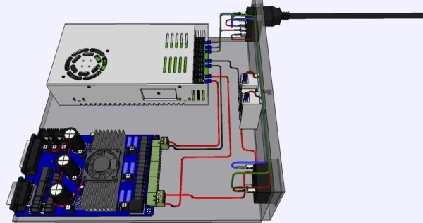
Instead, we can use a large relay (at this scale, they are generally referred to as contactors) to do the switching and control the relay from far away using a much lower voltage. This setup allows us to turn on the motor using a switch in just a 24 V circuit, which is physically far away from the high-power one. Lets take a simple example where we will be turning on an AC lamp by using a relay switch. In this relay circuit we use a push button to trigger a 5V relay, which in turn, complete the second circuit and turn on the lamp. (CFL) by using a relay switch. In this relay circuit we use a push button to trigger a 5V relay, which in turn, complete At the heart of this circuit is a 5V relay, which acts as an intermediary to switch the high-power AC load while being controlled by a low-power DC signal.Here's a breakdown of the components and their roles: Battery (9V): Supplies power to the control circuit. Switch (SW1): Turns the entire circuit ON or OFF. NPN Transistor: Amplifies the control signal to drive the relay.
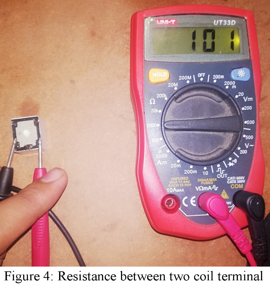
Reed Relay: Reed relays use a reed switch enclosed in a coil to control the switching action. They are compact and suitable for high-speed switching applications. Polarized Relay: Polarized relays have contacts that are polarized to ensure proper operation in DC circuits. They are designed to prevent reverse polarity issues. Now here in this post, we go deep and learn everything about how relays work inside electronic circuits how we can correctly find the pinouts of any relay using a meter and how we can wire it properly in circuits. Introduction. So if we want to flash a lamp, switch an AC motor or do any similar operation then relays are always useful for such

How a Relay Works and How to Use It in Circuits Circuit Diagram
Let's switch a lamp on and off using a relay in a circuit. We'll use both non-latching and latching relays. Relays are useful for using small signals to sw However a relay switch circuit can be used to control motors, heaters, lamps or AC circuits which themselves can draw a lot more electrical voltage, current and therefore power. The electro-mechanical relay is an output device (actuator) which come in a whole host of shapes, sizes and designs, and have many uses and applications in electronic