Arduino Lights Dimmer for Multiple Lamps Circuit Diagram
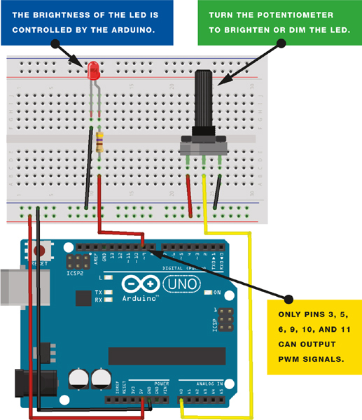
BlogArduino Lights Dimmer for Multiple Lamps Circuit Diagram Create a LED Dimmer. This example shows how to send data from a personal computer to an Arduino board to control the brightness of an LED. The data is sent in individual bytes, each of which ranges in value from 0 to 255. Circuit. Connect the 220 ohm current limiting resistor to digital pin 9, with an LED in series. The long, positive How to create a dimmer with Arduino: dimmable LED!In this video we're going to show you how to use the PWM output of the Arduino board to control the illumin To build a Simple Arduino LED Dimmer Circuit using PWM follow the below mentioned steps: Gather all the components mentioned in the above circuit diagram. Connect a regulated IC1 7809 to provide a regulated 9V DC to the Arduino board; Connect capacitor 100μF positive side between resistor 220Ω and red LED and negative side to the GND.

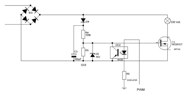
Hey guys, today we are going to learn how to make a light dimmer circuit using an Arduino board. There are two pushbuttons in this circuit, one is for increasing the brightness of the LED and the other one is for decreasing the brightness. So basically you can control the brightness level of any LED by using this project. Arduino light dimmer circuit: Project circuit schematic diagram is shown below. All grounded terminals are connected together. In this project I used the LM393 (dual comparator IC) for the zero crossing detection, the LM339 quad comparator IC also can be used. An optocoupler can be used for the same purpose( zero crossing detection) but I think Light dimmer dims light and glow light with defined manner.Components:1. Arduino Uno/ Nano/ Mega2. Switching Transistor: BC548/BC547/2N2222A or any NPN trans
Simple Arduino LED Dimmer Circuit using PWM Circuit Diagram
To make an Arduino LED Dimmer project, you need to use a PWM output pin and an analog input pin (for the potentiometer) 1- Set an IO pin as an output pin using the pinMode function. 2- Continuously read the analog input pin for the potentiometer 3- Map the 10-Bit ADC reading to the range of the 8-Bit PWM's duty cycle and write the value using This is a circuit that tells the Arduino (or another micro controller) when the sinus-wave goes through zero and therefore gives a defined point on that sinus wave. Step 6: Arduino Controlled Light Dimmer: the Software III. The code below uses the timer function rather than a delay and has been confirmed to work on the Leonardo as well Use an Arduino to make a dimmer and control the brightness of a lamp. Network Sites: Latest; Forums; Education; Tools; Videos; Datasheet; Circuit for the Arduino Lamp Dimmer. Lamp Dimmer Circuit. The figure above explains the positioning of the different electrical components in the circuit. Follow the circuit diagram to solder your dot board.